-
Notifications
You must be signed in to change notification settings - Fork 18
Assemble Talko_1.1
Talko 1.2 assembly page is located here https://github.com/deladriere/euro-modules/wiki/Assemble-Talko
Thonkiconn’ – 3.5mm Jack Sockets (x50) : Jacks connectors
Alternative 7segment Fischer Electronic receptacle : receptacle
Thonk potentiometer Alpha 9 mm Pots
Thonk Davies 1900h Clone Knob Davies 1900h
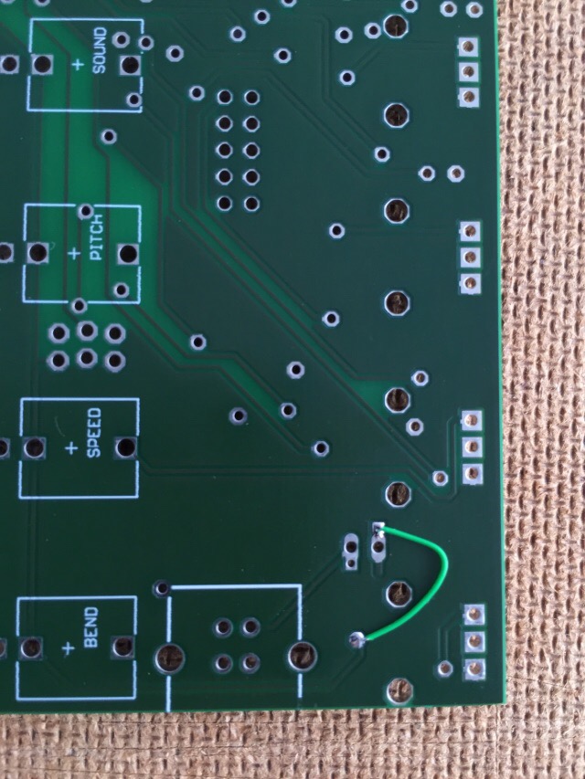
There is a missing +5V via that need to be fixed.
Add a little wire to connect these two vias :
Apply solder from the SMD side
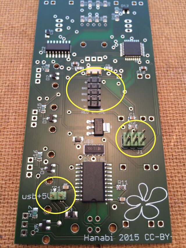
Start by adding the 3 connectors on the SMD side
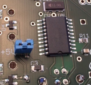
The power jumper is not necessary unless you want to take the module on the road or debug it before installing in the rack (I find useful to check the 7 segment led before soldering the other components)
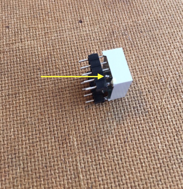
You need to solder all the 10 pins to the header to have it staying in place.
Do this before soldering on the pcb.
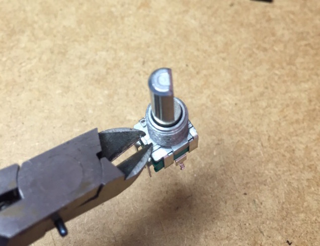
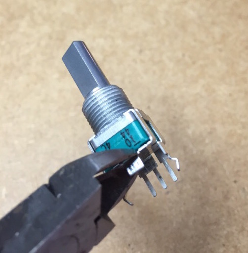
First remove the little nubs on each pots (to have the panel flush with the 7 segments display)
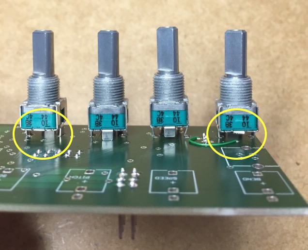
Cut/remove the foot on 2 pots (to avoid power shortcut via the panel's ground)
Place the pots in place
Notice the 2 pots without their foot
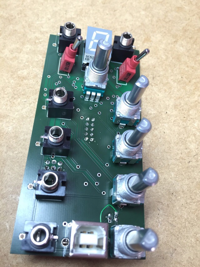
Add the component but don't solder them yet
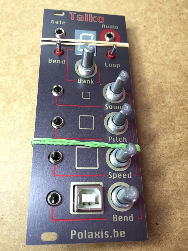
Add the panel and hold it in place with some rubber band and adjust the position before soldering
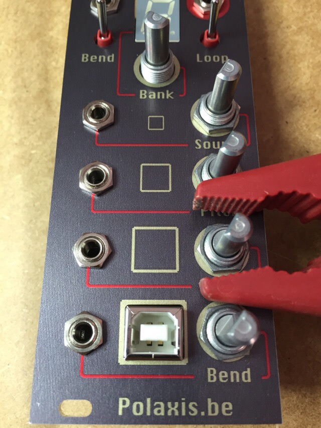
Center and fix element in place (I use a pair of plastic pliers to avoid scratching the panel)
Add the cap and you are done.
You can use the USB power to test the module by placing the jumper in place
If you leave it in place, you will have to switch your modular's power off and on to allow connecting the USB.
