-
Notifications
You must be signed in to change notification settings - Fork 18
Assemble Talko
(Talko 1.1 assembly manual is located here)

Attention: the 2 switches are differents but look almost the same. Read ahead for detailled instructions !
Thonkiconn’ – 3.5mm Jack Sockets (x50) : Jacks connectors
Thonk potentiometer Alpha 9 mm Pots
Thonk Davies 1900h Clone Knob Davies 1900h
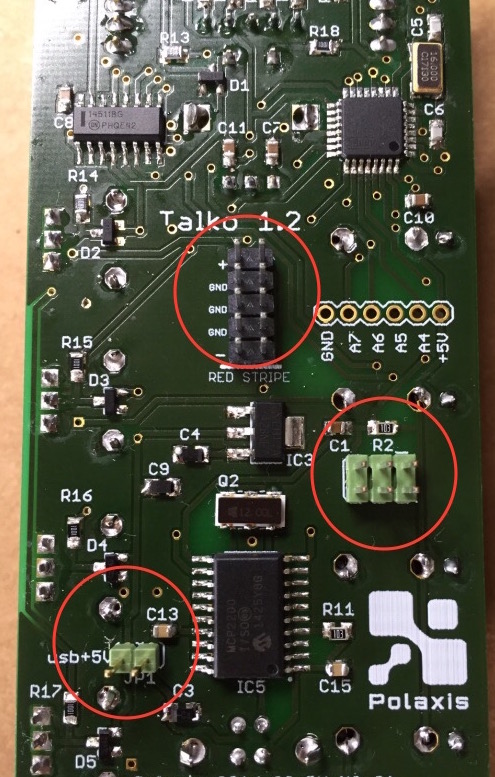
Start by adding the 3 connectors on the SMD side
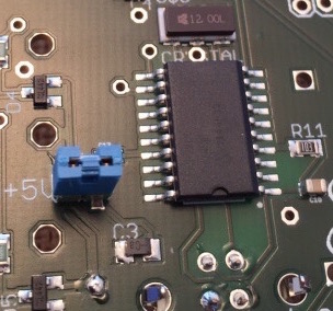
The power jumper is not necessary unless you want to take the module on the road or debug it before installing in the rack (I find useful to check the 7 segment led before soldering the other components)
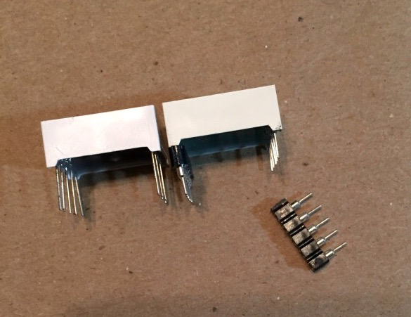
if you have the short legs version, Place the two 5 pins headers on the 7 segments display
Please note that the 7 segments displays random information until the proper software is loaded.
This is a normal behavior because no level has been set yet by the micro-controller and all entries of the BCD decoder are floating undefined.
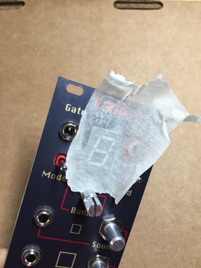
The rotary could short cut some via. Place some tape as illustrated here to avoid these short cuts
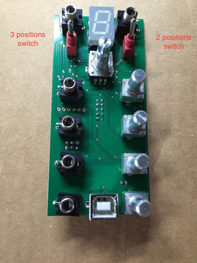
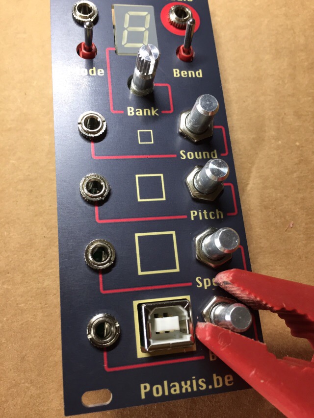
Please note that the 3 levels switch MUST be placed to the left and the 2 levels switch MUST be placed to the right. These two switches look exactly identical, so you need to test them to find which one goes where.
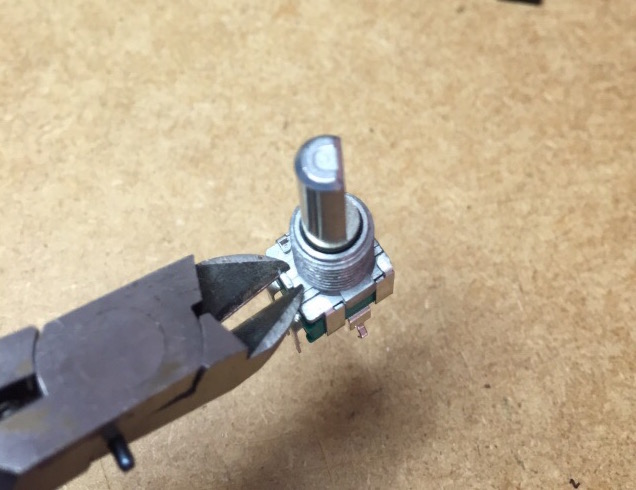
Please check if your pot models have any anti-rotational tag to remove. Use a pair of cutting plyers to remove the little nub on each pots (to have the panel sitting flush with the 7 segments display)
Add the component but don't solder them yet
Please make sure the 3 positions switch is placed on the left and the 2 positions is placed on the right.
Make sure the LED's dot is placed in the bottom right corner.
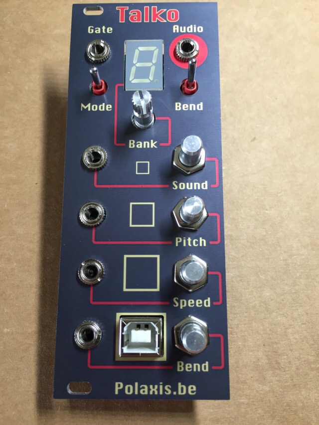
Add the panel and hold it in place by screwing the pot's nuts
Adjust the position of the different item.
Do not solder yet
(note that the rotary has no nut)
Use tape to make sure the LED display sit flat with the panel before soldering the header pins
Center and fix element in place (I use a pair of plastic pliers to avoid scratching the panel) before soldering
Add the knobs on the pots and you are done !
If you have the Davies 1900 lone knobs, don't let the knob sit all the way down because they will scrub on the nuts and add extra drag to the movement
The knob on the rotary must allows its switch to click, so don't fix it too low.
You can use the USB power to test the module by placing the jumper in place
You will need to remove it prior installing the module in the your modular case to allow resetting / declaring the USB port to the computer each time you plug it.
If you leave it in place, you will have to switch your modular power off and on to allow connecting the USB.
The kit pcb comes with the ATmega328p fuses set and the bootloader already flashed. This allows Talko to behave like an Arduino Uno board.
Note to Makers: if you are making you own Talko from scratch (not assembling the kit), you will need to set the ATmega328p fuses and flash the bootloader yourself using an ISP AVR programmer. The fuses seetings and the bootloader can be found here : https://github.com/deladriere/euro-modules/tree/master/Talko/Firmware
The next steps consist of uploading the firmware as decribed in the user manual
