STM32 32-bit microcontroller based 3-axis brushless gimbal controller board
scheme and design by OlliW (except of STorM32 v4.1)
v0.17: layout by Martinez and OlliW
v4.1: design by KrattWorks
latest board version: v3.3, v4.1
the STorM32 BGC boards and all other hardware published here are open source hardware, under the terms of the TAPR Open Hardware License as published by the Free Hardware Foundation, see http://www.tapr.org/ohl.html
the firmwares are free and the GUI is open source, for the details of the terms of usage/licenses see here
further resources:
- project web page http://www.olliw.eu/2013/storm32bgc/
- thread at rcgroups http://www.rcgroups.com/forums/showthread.php?t=2055844
- wiki for the documentation http://www.olliw.eu/storm32bgc-wiki/
Board specifically made for NT and TSTorM32 setups, with on-board motor drivers.
Boards specifically made for NT and TSTorM32 setups.
General purpose version.
Hat for the Raspberry Pi.
Series of stackable boards with 20x20 mm hole pattern: Main board, NT Motor-Encoder module, NT Triple Motor module, NT Logger module.
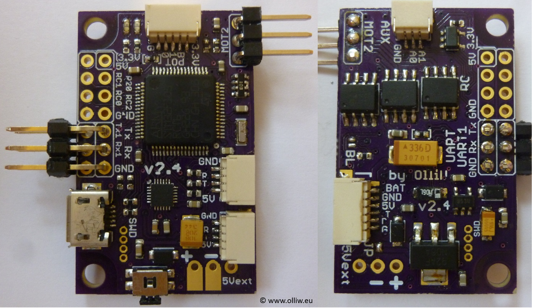
changes in v3.3:
- board specifically designed for NT and T-STorM32
- no motor drivers on board
- 3 NT plugs to make it easy to connect several NT modules
- NT-X plug carrying also the battery voltage
- 5 V power rail on the NT bus, with sufficient "juice"
- Rx&Tx on NT bus swapped, to avoid cable crossing to connect with NT modules
- support of stacking with a "high-power" extension board
- MPU9250 on board, spi (no i2c anymore!)
- firmware update procedure via USB
- ESP8266 port for WIFI connectability
- CAN bus port
- no BOOT0 button, smaller RESET button
- 0402 size parts
- board size as small as I could get it with a 2 layer design: 40 x 25 mm
- mounting holes, 3 mm diameter, 35 mm apart
changes in v1.3:
- voltage regulator in DPak package
- AUX2 instead of 3.3V pin at AUX port
- solder jumper to disconnect bluetooth led
- values of resistors R12,R13,R22 changed
changes in v1.2:
- minor issues of v1.1 corrected
- Futaba S-bus support
- Spektrum sattelite connector
- usb disconnect network modified to suite F4 processors (thanks ala42!)
- usb voltage protection diode added (as in v0.17)
- further minor changes in scheme and layout
changes in v1.1:
- reverse voltage protection added
- layout supports TC4452 motor drivers in DFN package for increased power capabilities
- high-side pnp open collector output for driving an IR led added
- additional connector for I2C#2 port added
- larger solder holes and pads for battery power connection
- improved pin arrangement for easier use
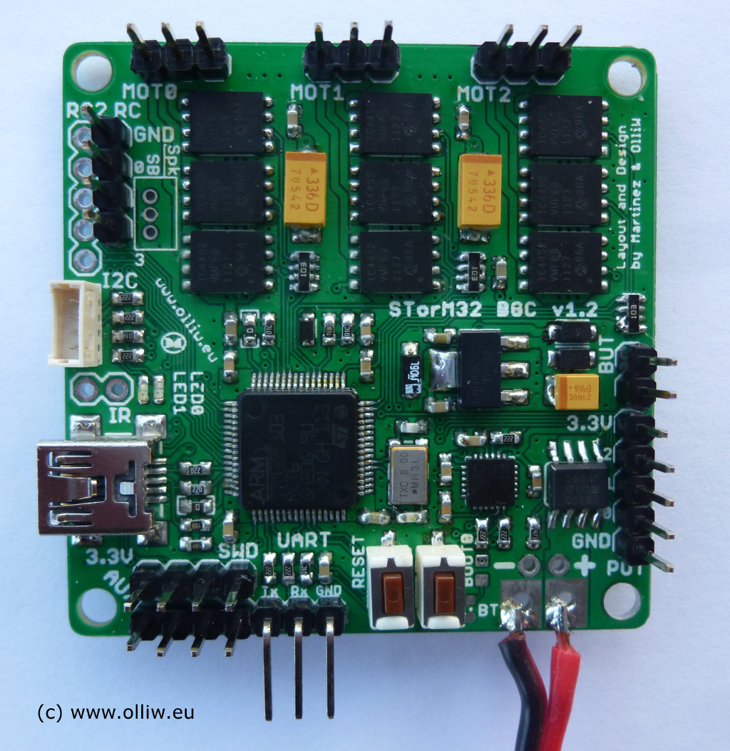
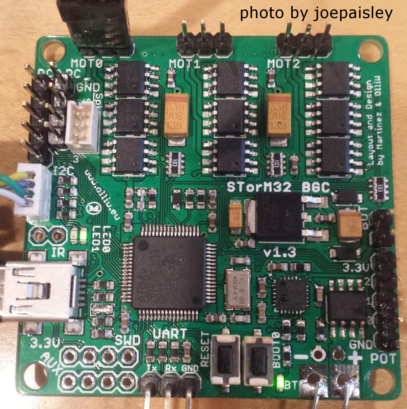
pictures of the v1.2 board (with DFN packages) and v1.3 board (with SOIC packages):


