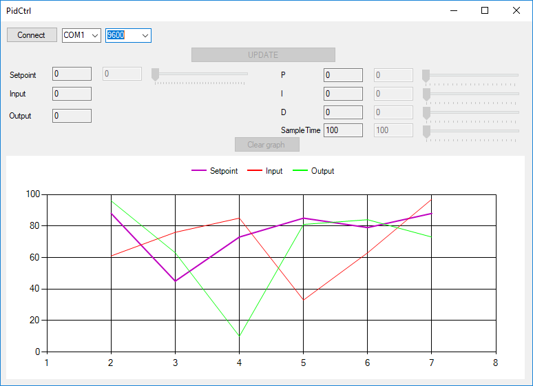
This is greatly inspired by the "Dark room experiment" used to demonstrate the use of a PID controller : https://www.instructables.com/id/Arduino-PID-Library-Luminosity-Control/
- Setpoint (0-255), Sample time (ms) as well as P, I and D coefficients can be adjusted on the fly
- Setpoint, input (LDR) and output (LED) values are displayed on the graph
- README.md -> that the file you are reading now
- Screenshots -> behavior of the app
- Schematics -> Fritzing schematics and captures
- ldr_read -> Arduino project
- PidCtrl -> Visual Studio project
- PidCtrl\PidCtrl\bin\Debug\PidCtrl.exe -> latest version of the Windows app
- LDR_calc.xlsx -> File to test different resistor values for the LDR
- A0 - R1 - GND
- A0 - LDR - Vcc
- D3 - LED - R2 - GND
- R1 sets the range of the input and depends of the LDR used.
Measure the LDR value when in the dark and illuminated by a bright light.
For example for R1=100kΩ, Rhigh=800kΩ and Rlow=5kΩ the voltages would be :
- Rhigh/(Rhigh+R1)*Vcc = 800/(800+100)*5.0 = 4.44V
- Rlow/(Rlow+R1)*Vcc = 5/(5+100)*5.0 = 0.24V
- Keep in mind that the function is not linear (see LDR_calc.xlsx file)
- R2 limits the LED current : 220Ω is a good value and is calculed as follows :
- R = (Vcc-Vf)/I = (5.0V-2.8V)/0.01A) = 220Ω
- Vf being the forward voltage drop of the led (Red ~2.8V) and I the desired current (10mA), that's the worst case scenario as LEDs tends to have a higher voltage drop and the Arduino Nano can deliver up to 20mA per pin
- Reduce external light if oscillating occur (especially artificial like fluorescent tube)
https://www.arduino.cc/en/main/software
https://visualstudio.microsoft.com
- Author : Jimmy Caille
- Email : [email protected]

