This is an experimental project. There is a bit of risk here since this combines electrical components and water. Use at your own risk. We are quite lucky in that we have a pool in our backyard. It's not ostentatious or ridiculously expensive; it was something my wife has worked for several years to obtain, at my constant opposition. I eventually capitulated when she agreed to my terms of above-ground only, so it could be easily removed if need be, and so it was considerably cheaper. So now we have a pool. My wife constantly wants to know the pool temperature because she is fickle. She only likes to swim at certain water temperatures -- usually when the water is akin to a bath. We had, for a moment, a cheap (well, not really) wireless thermometer that transmitted the temperature to a convenient display in the house. But, it lasted only a year. I didn't want to keep replacing it, so I decided to build this thing.
A small Arduino-based microcontroller that periodically reads the temperature from a sensor and uploads the data to a website. This was the original goal, and this was satisfied rather quickly... but things being as they are and people being themselves (namely, me being me) the goals have expanded to include an creating an Alexa skill. Why? So we can ask our Amazon assistant to report the pool temperature. This has the added bonus of also including a time difference analysis -- if the temperature readings are long in the tooth, Alexa will says so, which means something might not be working correctly, such as a low battery or faulty temperature sensor. This solved another problem which was how to report the voltage supply of the Arduino, which is highly regulated so it's not exactly easy to discern. But, forget that. Move on to...
Ok, so before you move on, you will need:
- Arduino-based board with ESP32. I like the [Adafruit Metro Airlift Express] (https://www.adafruit.com/product/4000) because of the extremely long name (seriously, though come one).
- Temperature Sensor of the DS12B20 (sensor only) or DS18B20 (sensor and terminal board) variety. I used the DS18B20 as it comes with a with terminal board that alleviates the need for an additional pull-up resistor and has JST hookups. If you don't need that, just get the sensor.
- Hookup wire
- Waterpoof project box
- Cable Gland, PG7 You'll need at least one of these. But get a few because they are cheap. You might also want a few sizes. PG7 will fit the temperature sensor cable. Depending on how you power your Arduino board you might need some additional glands of varying sizes. I'll leave that up to you. Just know that you are not going to be powering this thing with a battery unless it's a very large battery.
Build the circuit according to the simple schematic below. I have zero knowledge of how to draw a proper schematic and while I could bother myself with getting fancy, this is all I can muster. 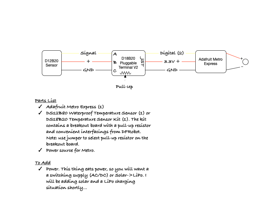
Here you can see the terminal board, which shows the left side wiring from the sensor (red/black/yellow) into the wiring block, and the JST connection on the right.
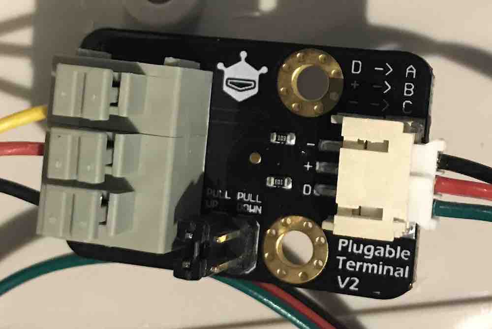
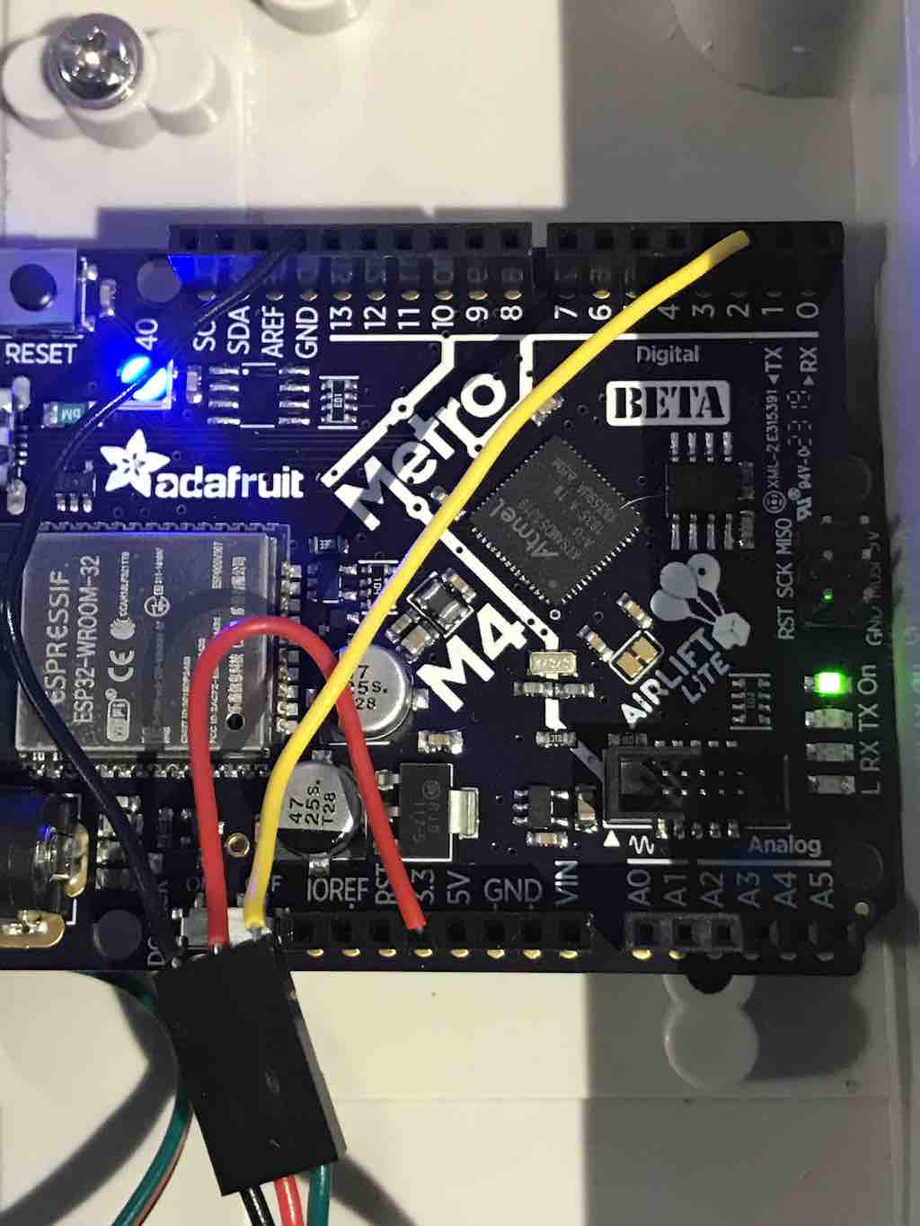
The JST connection is connected via hookup wires as black/black/GND pin, red/red/3.3V pin, and green/yellow/Digital 2 pin as shown in here:
If you've never acclimated yourself to CircuitPython or Python in general, then you've come to the right place! Only because I have a link to CircuitPython so someone else can tell you. I don't have time for that. So, download Mu, install CircuitPython if necessary and try a Hello, World! program. Before you move on, you should have wired up your parts and have successfully run the blink program. Now you're ready to rock.
Your sensor is going to capture data. Sweet, sweet data. Now... where to put it? Data without context or accessibility is useless, so let's turn this data into information! Luckily, the fine folks over at Adafruit already have something we can use, so create an account and then create a feed -- note that I'm linking to the tutorial on how to create a feed because there are more steps than I care to recreate here. Just FYI: you can make your feed public or private and it won't affect the operation of the temperature sensor upload code. But, if anything outside of this code needs to access your feed, you may need to make it public. By the end of this paragraph, you should have the following information:
- AIO (Adafruit IO) key
- AIO Username
- AIO Feed Name
Armed with this information, you should now clone this repository. Now it's time to make it your own!
- Modify secret.py and add your AIO information. While you're here, you should add your Wifi information too.
- Modify code.py and... wait, you don't actually have to modify anything! Huh.
- Upload code.py and secret.py to your Metro board, and see what happens! Hopefully everything is uploading correctly. If not, you can check out the REPL debugger and fiddle a bit. You might want to change the value for the sleep timer at the very end of code.py so it doesn't sleep as long but I wouldn't go any lower then 15. Once you're populating data to AIO from your temperature sensor, it's time to move on!
Yes, I'm sure you thought we were done with fabrication, but sadly we are not. We have a few more things to assemble.
- Drill holes in the project box to fit your gland(s). Here's a reference chart. A PG-7 should be about 11.5MM (I didn't tap mine).
- Fit glands using this order: Gland > O-Ring > Project Box Hole > Gland Nut
- Temporarily disconnect DS12B20 from the board.
- Insert DS12B20 cable into gland closure nut (this has a rounded end), then feed through the gland/box/gland nut, wire back up to board.
- Leave a little slack inside the box for the DS12B20 wire, then tighten the closure nut.
- Repeat the gland-drill-cable for your Metro power supply. I hope you got the right kind of waterproof power supply situation worked out.
- Seal the box using the supplied closure screw doodads.
Take this puppy outside, dunk the sensor in your skimmer box or over the side of the pool, or where ever might be good. Wear rubber shoes and connect the power to the box and hopefully your NeoPixel goes blue and you're transmitting data.
- Wire up a PV cell to a charging circuit for resuppling precious volts to a LiPo battery for powering the Metro. As soon as my parts come in, you can bet I'll be updating this codebase.
- Do you have an Amazon Echo, Tap, Dot, or other Alexa-powered device? Check out the Lambda function I built for interfacing to the AIO data. You can take this and whip up your own Alexa Skill and deploy it to your device. Note: there is a lot more involved in this than is alluded to in the Lambda code -- consider yourself warned. I make come back and document that part at some point...
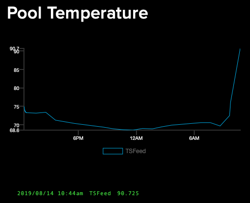
- Create an AIO dashboard so you can see your temperature readings over time, like so. really my pool doesn't have a 20 degree temperature swing, I just brought the sensor inside so I could take pictures :-)
Have fun!