Thanks for your interest in this project. We would like to inform you that we have noticed some bugs in the hardware part of this project. We cannot promise immediate support but we plan on fixing it as soon as we get time out of our living jobs. Appreciated
A reflow Hotplate for DIY SMD assembly.This device is created as a Low-Cost solution for DIY reflow assembly of SMD components.
- Compact Design
- 9V-12V DC Input via regular DC Jack
- 100mm x 100mm Reflow area
- High-Current protection
- PIC16F MCU to control the system
- PIC programmer Interface
- I2C LCD Support
- Detachable design Click here to see more
- Temperature Probs
- UI with LCD and Pushbuttons for controlling the system.
- Low Cost & Portable
Reflow soldering is a process in which a solder paste (a sticky mixture of powdered solder and flux) is used to temporarily attach one or thousands of tiny electrical components to their contact pads, after which the entire assembly is subjected to controlled heat. The solder paste reflows in a molten state, creating permanent solder joints. Heating may be accomplished by passing the assembly through a reflow oven.
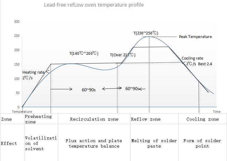
The reflow curve of the temperature of a certain point on the SMA with time when the SMA passes through the reflow oven furnace. The temperature curve provides an intuitive method to analyze the temperature change of a component during the entire reflow soldering process. Below is the proper reflow curve a heater should achieve for perfect soldering of components.
The hOtpLaTe r0.1 manages to acheive this temperature curve by adjusting the switching duty of MOSFET which results in variation in heat. The temperature sensor continously reads the temperatures and sends back to the Microcontroller.
This board is created considering all the potential issues and major use cases. The advantange is that you can use it either as a whole system by simply plugging the power in and starting the system OR You can detach the controller and Coil area of the PCB (separated by cut-lines).
This makes it highly portable and Tweakers friendly.
The standard PCB material is FR4 which is very reliable in handling higher temperatures but it may not be very long lasting if being used very often. So, I came up with a backup plan and designed it in a way you can just cut the controller portion away from the coil area and use the controller with any OFF the SHELF heating element like alluminum plates.
You Can manufacture the PCBs from PCBWay. Check Out PCBWay
Note: I am not affiliated with PCBWay. However, I just like their service and build quality.
It is super convenient to assemble the Hardware & Components specially if you ordered the Stencil alongwith PCBs. After opening the Project in KiCAD, you can just scroll through the BOM and place components with respect to their designators. OR If you wish to order assembled PCBs, I optimized the BOM to make it super smooth and easy to source components. It is requested to please Open up an Issues if there is any stock outage or Manufacturing Problems.
- Program the Microcontroller using CP210x/CH340x/FTDI based USB to serial converters.
- The ARDUINO IDE can be used to Program the Microcontroller.
- Power Up the Board using a PSU with 6-12V @ 2A Ratings.
- Give Hotplate Enough time to Heatup and cooldown. Any Forced Cooldown solution is highly NOT RECOMMENDED as it reduces the Life of FR4 material.
- If Temperatures Higher than 270C are desired, feel free to breakdown/cutdown the Controller portion and Heating Element to avoid controller assembly meltdown. (In such case, desolder the Temperature sensor and extend it to the bottom of the hotplate using wires).
Contributions are what make the open source community such an amazing place to learn, inspire, and create. Any contributions you make are greatly appreciated.
If you have a suggestion that would make this better, please fork the repo and create a pull request. You can also simply open an issue with the tag "enhancement". Don't forget to give the project a star! Thanks again!
- Fork the Project
- Create your Feature Branch (
git checkout -b feature/AmazingFeature) - Commit your Changes (
git commit -m 'Add some AmazingFeature') - Push to the Branch (
git push origin feature/AmazingFeature) - Open a Pull Request
- Proof of Concept
- Research & Information
- Finalizing The Idea
- Schematics
- PCB Design
- Firmware Development
- Validation & Testing
- Documentation
- Future Improvements
This Hotplate is based on Regular FR4 materials that degrade over time due to excessive heating. In near future, it is desired to implement the same Idea on Alluminum Base PCBs. ISSUE: Alluminum would act as heatsink not letting the plate to heatup/quick cooldowns. Community please step in.........
This Project is designed under General Public License V3.0 See LICENSE.txt for more information.


